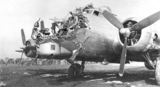
Boeing, the right plane. Boeing 737–500 cockpit overview (28 photos)
Boeing 737 aircraft are the most popular non-wide-body long-haul aircraft in the world.
As of September 2009, 6,170 Boeing 737 aircraft had already been sold.
These aircraft are usually divided into three generations: Original ("Original" - modifications -100, -200), Classic ("Classic" -300, -400, -500) and New Generation ("New Generation" -600, -700, –800, –900).
The Boeing 737 Classic family consists of the 737-300, -400 and -500 models, which differ slightly - mainly in length and passenger capacity.
The first aircraft of the -300 series was delivered in 1984, and the last, -500, in 1999.
It seems that it was precisely thanks to the almost two thousand aircraft of the Classic series produced, which were much more reliable and safe than the Original, that the Boeing 737 became a bestseller.
The 737 cabin will be examined using the example of the 737–500 available in our company.
It looks, of course, much more modest than the Airbus 320.
General view of the cabin:

As you can see, compared to the under-plane A320 :), it even has steering wheels.
Of course, Boeing is a real airplane.
For real men who know how to compete with technology.
To the left of the PIC's helm there is another steering wheel - this is to control the turn of the front leg at large angles during taxiing.
You can immediately look at the main steering wheel:

On his horns:
on the inside there is a numerator where the flight number is usually set (so that the pilot does not forget during negotiations with dispatchers),
from the outside:
double push switch for the electric drive of the stabilizer shift,
autopilot off button,
microphone activation rocker, which has two positions - in one, the microphone is connected to the radio station for transmission, and in the other, for transmission for internal communication (or with ground personnel). This switch is located on the dashboard side and is not currently visible,
in the middle there is a clothespin for attaching all sorts of useful pieces of paper, for example, diagrams of the runway approach and go-around.
By the way, it should be noted that the steering wheel does block some instruments.
Behind the helm, in front, there is an instrument panel with the main flight instruments:

Since the plane is classic, its instruments are in many ways classic dial “alarm clocks”.
On the left edge there are three pieces:
clock, airspeed indicator, radio compass.
Next are two displays:

The top one is a replacement of the attitude indicator (now the inertials are simply turned off and therefore there is no picture).
It also has a speed bar on the left, and points on the right and bottom to indicate deviation from the glide path.
and at the bottom right - radio altimeter indication.
The lower (navigation) display displays the flight plan, aircraft marks from TCAS, a picture from the radar and something else.
Further left:

top left - I don’t remember what :), top right - three indicators of the passage of radio beacons (during landing).
Then below from left to right:
barometric altimeter, spare altimeter with airspeed indicator, spare (backup) attitude indicator.
variometer (vertical speed indicator), plate for the correspondence of foot echelons to meter levels (not included in the standard delivery),
fuel gauge indicators for the tanks (two wing ones and a central one in the middle).
The co-pilot also has the same instrument panel.
Between these boards is the central board:

The emerging transition to electronic display of instrument readings is already noticeable here. But for now, “alarm clocks” have been replaced only by LED indicators.
At the very top is an indicator of the Yaw damper operation (this is a yaw damper - to suppress the self-oscillatory movement of the aircraft along the course).
Below are various warning lights.
Even lower, the left side is an indication of engine operation:
fan speed (N1),
gas temperature (EGT),
engine high pressure compressor speed (N2),
fuel consumption.
Panel in the center (top to bottom):
outside air temperature,
engine oil pressure,
oil temperature and quantity (in percent),
rotor vibration,
pressure in hydraulic systems A and B; the amount of liquid in them (in percent).
Right part:
flap position indicator (two arrows - for left and right flaps),
switch and indicator for automatic anti-skid brakes of the main wheels,
switch for the intensity of automatic braking during landing (RTO - aborted take-off).
And a little more to the right, closer to the co-pilot, a brutal landing gear release/retraction handle sticks out.

A hydraulic tap is no good for you.
At the bottom of this handle there is a bracket (red) to overcome the mechanical locking of the handle (if necessary).
The mechanical cable wiring for emergency landing gear release (in the absence of pressure in the hydraulic systems) ends with handles located in the hatch in the floor at the entrance to the cockpit (on their side of the door :)).
Below the central instrument panel are two MCDUs (multi-function display units) for entering the flight route.

Some systems are also tested through them, but since this aircraft is much less electronic than the A320, the functionality of the MCDU is much lower. For example, our mechanics on the 737 practically don’t use it (only avionics specialists sometimes), while on the A320, without this computer, there’s practically no way.
In the middle, between them, is the weather locator control panel.
The sticker below informs pilots that the engines on this aircraft are configured for increased thrust - approximately 9 tons each.
Even further back, on the way to the central console, is our everything:

Here are the controls for engines, wing mechanization, fire protection system and all sorts of other things.
Everything can be pulled (and some things even move on their own), and everything is connected directly with steel cables to different parts of the aircraft.

The parking brake release sticks out at the bottom left.
to the right and above are two throttles (engine control levers, or rather, their thrust) with steering control levers on them in front (reverse control levers). The button at the end of the throttle switches off the autothrottle, and the button sticking up turns on the maximum mode for both engines for a missed approach or the fastest takeoff.
To the right and further sticks out the control handle for spoilers (air brakes),
the rightmost and closest is the flap control handle.
Below on the same control panel, on both sides, there are drums connected to the stabilizer shift control cables:

The reels have retractable handles for manual repositioning of the stabilizer in the event of electrical control failure.
To the left you can see the toggle switches for disabling the automatic stabilizer trim control.
Fire protection panel:

Two handles for engines (on the sides) and one for the APU (in the center).
When pulled up, the corresponding engine is de-energized and the supply of fuel and hydraulic fluid is cut off.
To discharge the fire cylinder, turn the handle to the side.
Toggle switches - for checking parts of the system.
Central control.
Front to back.

On the left side (this is the middle of the remote):
at the top is a surveillance camera screen for the door area near the pilot’s cabin. Since there are no tables on the Boeing, it is very convenient for everyone to put various little things on the screen, which is why it is worn out.
Below is the control panel for the trunk fire extinguishing system.
even lower is the control of the TCAS aircraft collision avoidance system.
Now the right side:
on top - control panel for VHF radio station,
Below is radio navigation control.
even lower is the control panel for displaying information on the navigation display and setting the altitude for turning off the autopilot.
The left panel of the PIC is completely similar to this shown right panel of the co-pilot.
Next, the central console (more back in flight):

Left side:
on top - roll and heading trim control,
Below is the control panel for the HF radio station.
Right part:
control panel for audio devices (radio stations, service communication with flight attendants, communication with ground staff, ...)
below is the ADF frequency setting panel... This is... uh... automatic direction finder :)) translated.
at the very bottom - control of the electric lock of the cockpit door.
In general, on this plane the co-pilot is allowed too much :)
It also has a closer control for the door lock, and the oxygen tap is located near it, so it can literally shut off the oxygen to the PIC :)
You couldn’t do this on an Airbus - there the oxygen is closer to the captain, and the door lock too.
The most delicious thing, as usual, is the ceiling panel :)

This is where they (the designers) came up with protruding toggle switches, switches and buttons :)
At the bottom of the panel there is an external light control:

From left to right:
landing external (on the wing) and internal lights,
side taxiing lights,
taxi light on the front leg,
APU start and stop switch,
switches for starting engines and selecting the operating mode of the ignition system,
strobes, navigation lights, flashing beacons, wing lighting, landing gear bay lighting.
Below is a spare magnetic compass:

Left lower part of the ceiling panel:

top left - fuel temperature indicator in the left wing tank,
on either side of it there are lamps indicating the position of the fuel valves (I don’t remember which ones. Probably engine ones).
Below is a valve for piping the fuel supply systems of the left and right engines.
below are the switches for the fuel pumps of the tanks (two for each tank).
The left tank pumps also power the APU, so usually the rear left tank pump is always on.
Bottom right:
gas temperature indicator at the outlet of the APU and ammeter of the APU generator.
Above are switches for contactors connecting to the network of engine generators, the APU generator and the ground power supply.
Above are ammeters of electric motor generators.
The AC system on the aircraft is 115 V, 400 Hz.
Above this panel:

Top to bottom left side:
evacuation signal,
control panel for connecting a spare hydraulic system to power alternative control of flaps, rudder, spoilers. Turn on the yaw damper.
radio navigation control and switching the display to a working inertial navigation system if the second one fails,
switching something else to a working one :)
Top to bottom right side:
DC ammeter (for battery) and voltmeter, APU generator frequency meter and AC voltmeter,
DC and AC voltmeter switches, battery switch, kitchen equipment power switch,
control panel for connecting a backup AC voltage source,
in the same place - toggle switches for mechanical disconnection of the shafts of the alternating voltage generators of the engines from the drive boxes of the motor units,
oil temperature indicators in constant speed drives of engines
(the fact is that the engine rotors rotate at different frequencies depending on the operating mode, and the voltage frequency of the electric generators of the engines must be constant).
And at the very, very top of the ceiling there is a duplicate indicator of the slats position:

Now - the right side of the very top of the ceiling (even above the ceiling panel):

On the left is the control panel for inertial navigation systems (of which there are two).
to the right: at the top is a toggle switch for turning on service points for communication with the cockpit (there are many of them around the plane - near the APU compartment, near the engines, somewhere else...), below is a toggle switch for turning on the cabin lighting;
even more to the right: at the top is the control panel for audio devices of the third occupier,
below it are buttons for turning on the electronic engine units,
below is an electronic pressure gauge in the crew’s oxygen cylinder and a toggle switch for discarding masks for passengers,
Below them is a duplicate indication of the position of the landing gear and a plate of the minimum permissible oxygen pressure in the crew cylinder depending on the number of crew members in the cabin.
rightmost part:
emergency recorder switch
and test buttons for speed and stall warning systems.
Right upper part of the ceiling panel:

on the left: a window for the central console illumination lamp, brightness controls for the illumination of gas station panels and the ceiling panel.
to the right: on top there is a control panel for heating the static and dynamic pressure sensors, as well as the cockpit windows; Below is control of the anti-icing systems of the engines and wing (they are all airborne).
the right side controls the air conditioning system in the cabin and in the cockpit (they work partially mixed, but the left pack works more for the pilot’s cabin, and the right one works mainly for the cabin; therefore, on the ground the plane is heated and cooled most often with the right pack). At the top are indicators of the position of the hot and cold air mixing dampers, between them is a temperature indicator switch to the “supply pipeline” and “interior” positions; Below is a temperature indicator, even lower are two temperature setpoints (now they are in the position of direct manual control of the dampers, and most of the circular arc is the temperature setting in the cabin for its automatic maintenance).
The panel below it:

left:
top - selection of normal or alternative avionics cooling fans (that is, electronic equipment),
below is the operating mode of the hazard warning lights in the cabin,
even lower are the toggle switches for turning on the “Don’t Smoking” and “Fasten Seat Belts” displays in the cabin.
to the right:
at the top - indicator lamps for insufficient hydraulic fluid pressure in hydraulic systems and toggle switches for turning on their electric pumps and opening valves to the motor hydraulic pumps;
below are indicator lamps for open doors and hatches;
at the bottom is the control panel for the cockpit voice recorder (the microphone is on the left under the mesh).
the rightmost part is the control of the air conditioning system packs (pressure indicator pressure gauge in the lines, toggle switch for the air recirculation fan, toggle switches for the valves for supplying air to the packs and taking them from the engines and APU (bottom in the middle). Indicator lamps).
The lowest and rightmost part of the ceiling panel:

left:
at the top are signals for calling the flight attendant and ground staff;
a system for spraying the windshield with a water-repellent liquid (now deactivated on all types of aircraft),
below - turning on the co-pilot's windshield wiper.
the very bottom part of the panel has already been explained before.
in the middle there are indicators of “cabin altitude” and the rate of change, a button to turn off the sound alarm;
the rightmost part is the control of the system for maintaining air pressure inside the aircraft (on the left is the automatic operating mode, in the middle is the spare mode, on the right is manual control of the cockpit air release valve; at the bottom right is control of the system’s operating modes).
And now only a little remains - all sorts of little things.
In the lower right part of the photo there is a knob for adjusting the distance to the pedals:

(this is right under the dashboard of the corresponding pilot)
Pilot's seat (riveted from real tin with real metal rivets)

Levers in the most unexpected places, continuity of design with military transport aircraft and, at the same time, with the B-777. I think the B-787 will have the same riveted steel chair :)
On the left side, the red one is the co-pilot’s oxygen mask.
Next is a microphone to scare passengers (you can make other communications).
Emergency flashlight.
Above it, a cable for electric heating of the window glass stretches to the window.
Behind the pilots are gas station panels (fuse circuit breakers):

Fire extinguisher.
And finally, directly above the pilots:

at the top left there is a black piece of the ceiling panel, below there is a loudspeaker (can broadcast the same thing as in headphones),
to the right, at the top, there is a hole for the illumination lamp of the upper part of the gas station panel, under it there is a hatch with an emergency rope for lowering out of the window in case of emergency,
To the right of all is the grille of the ventilation system opening.