I'm talking about the design of SGM-3 capacitors (8 photos)
Good day, dear readers. I continue to review the design of various radio components for you. Today we received the SGM-3 capacitor for review. 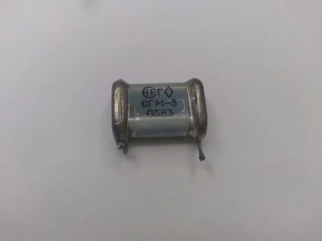
SGM-3 capacitor, evil people stole its legs.
The SGM-3 marking is deciphered as follows. S - mica, G - sealed, M - small-sized. 3 is the development number.
Let's try to disassemble this capacitor as soon as possible. First of all, let's try to remove its terminals. 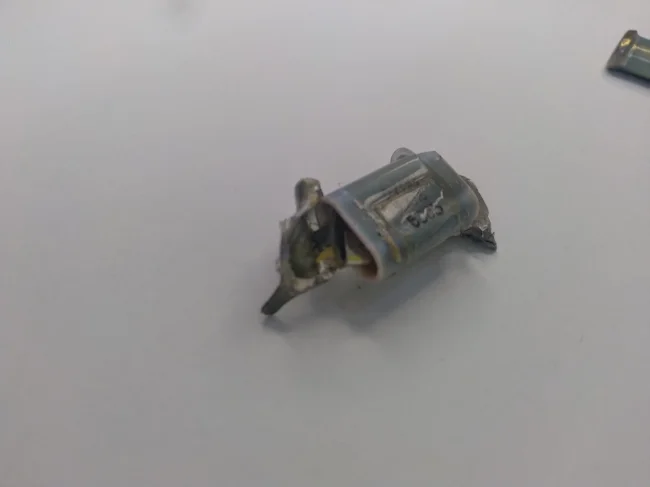
We see that the ends of the terminals are connected to the internal cassette of plates 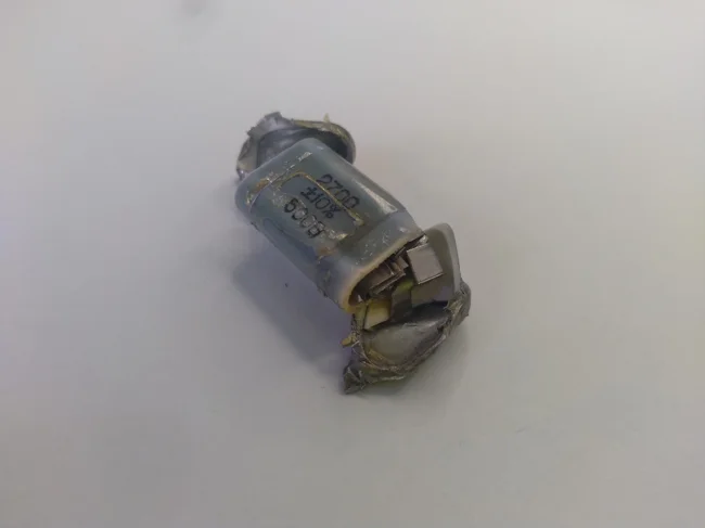
The cassette inside is fixed to the terminal structure
The terminals on the ends are quite soft and easy to remove, although they are heavily deformed. 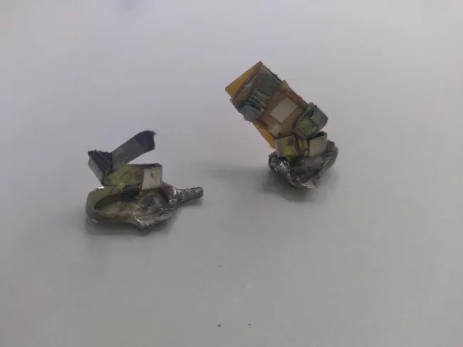
I removed the capacitor leads. The plate cassette came out with one of the leads
When removing the capacitor leads, the mica plate cassette, which is attached to the terminal structure, came out of the ceramic capacitor body along with one of the leads. 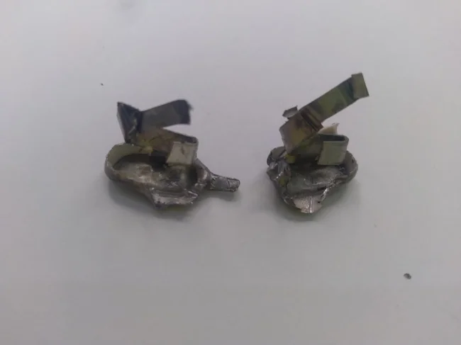
This is what the disconnected leads look like
The photo above shows the leads disconnected from the capacitor body and the mica plate cassette. 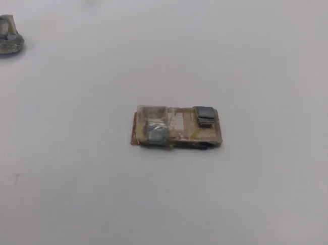
A cassette of mica plates, view from one side 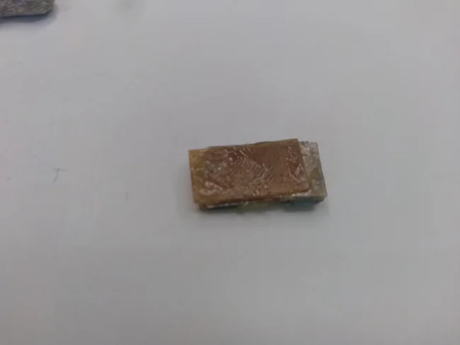
A cassette of mica plates, view from the other side
Let's now take a closer look at the cassette of mica plates. It is a stack of mica plates. These plates act as a dielectric in this capacitor. Each plate has two strips of foil, these strips act as the plates of our capacitor. All these mica plates with foil strips are collected in a stack to set the capacitor capacity. All this majesty is generously flavored with oil, in my case the oil was odorless. 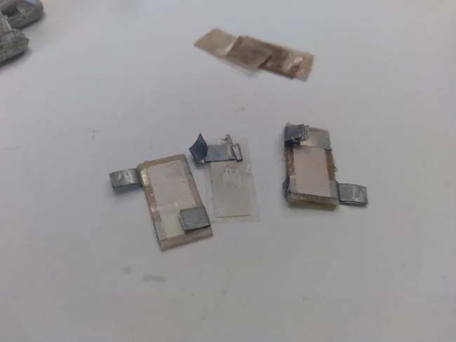
I took apart a stack of mica plates
This is the simple design of the SGM-3 capacitor, in its logic it is somewhat reminiscent of the design of the KBG-I paper capacitor, which we talked about earlier on this channel.


