Understanding the design of the RES54 relay (9 photos)
Hello, hello. Today I have a review of the RES54 relay. This relay is made in a sealed case and is designed for switching AC and DC electrical circuits. 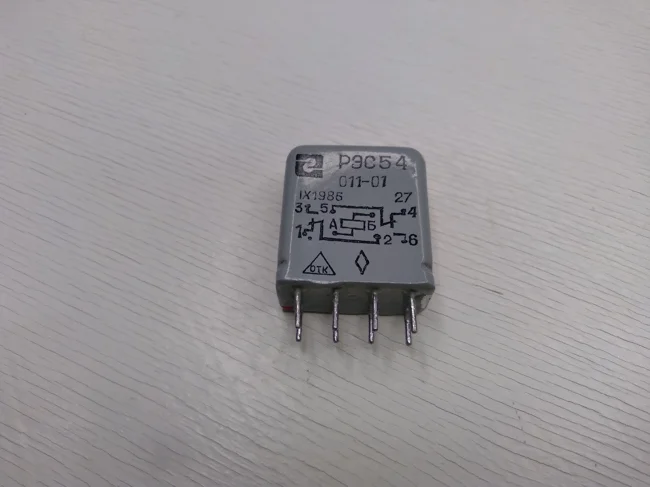
RES54 in all its glory
The numbering of the contacts of this relay is performed according to the diagram shown in the figure below. 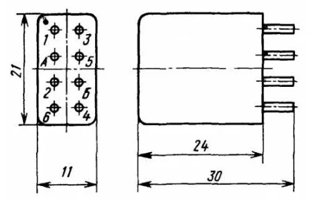
Relay contact numbering RES54
The correct positioning of the relay to determine the contact numbering can be determined by the point located on the diagram in the upper left corner. In reality, it is a point painted in red. 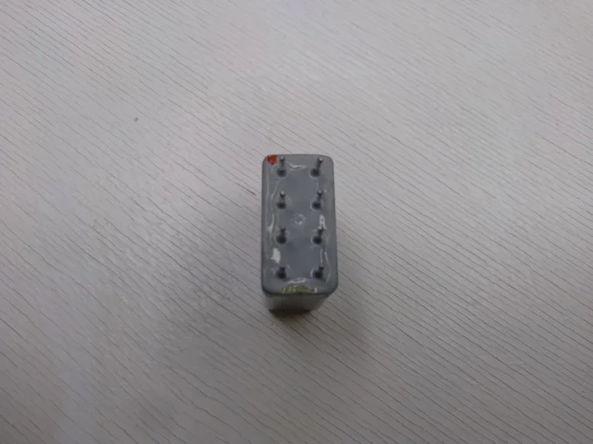
The red dot allows you to determine the numbering of the contacts of the RES54 relay
The operation diagram of this relay is shown in the diagram below: 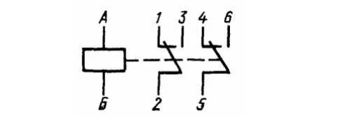
Schematic diagram of the RES54 relay
In principle, this diagram is applied to the side of this relay, but it seems to me that in this figure it is shown in a more understandable form. From this diagram, we can understand that by applying or removing voltage in the A-B circuit, we can control switching in two circuits:
2-1 or 2-3
5-4 or 5-6
Now that everything is clear with the general operating principle of this relay, let's try to see what is inside it. It is not so easy to do this, the case of this relay is cast and sealed, its upper part will have to be cut off with a hacksaw to get to its insides.
I cut off the relay case with an ordinary hacksaw, this difficult task took me about 10 minutes, since I worked without a vice. During this time, I managed to catch several strange looks from my wife, who did not understand what nonsense I was doing again.
Judging by how difficult it was to cut off the case of this relay, it is made of steel. 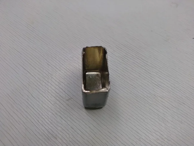
Cut off the RES54 relay housing
Under the housing we see the internal appearance of this relay. Pay attention to the photo below, in it you can see that contact A is connected to the coil winding located at the top of the relay. 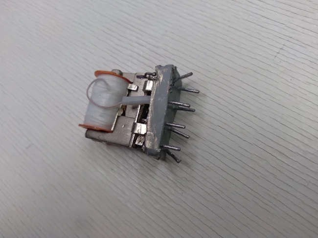
Connecting contact A inside the RES54 relay
And in this photo you can see how contact B is connected to the coil at the top of the relay. 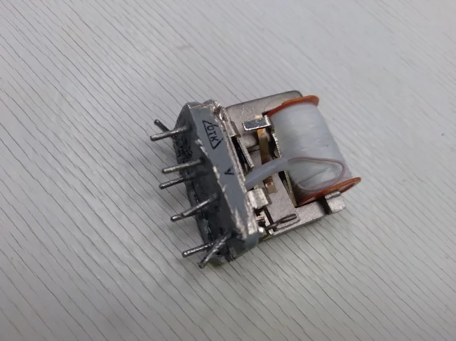
Connecting contact B inside the RES54 relay
What do we get if we apply voltage to contacts A and B with this relay design? Correctly, we get a regular electromagnet.
By applying or removing voltage to contacts A and B, we will attract/release the anchor located below the coil. And the anchor will exert a mechanical effect on the contacts located below and will switch them. 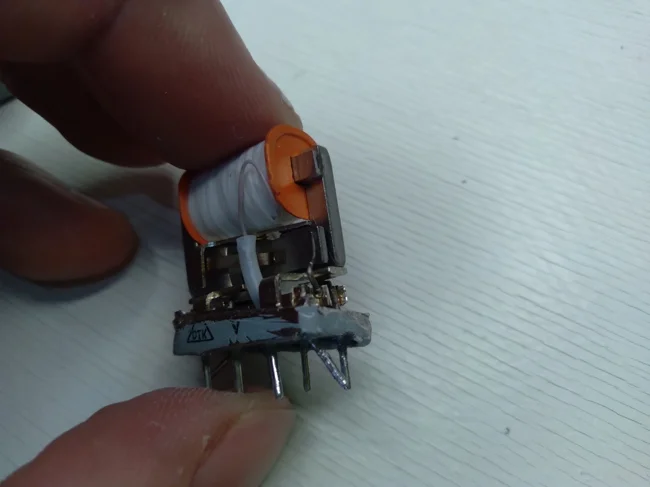
The anchor is located below the coil 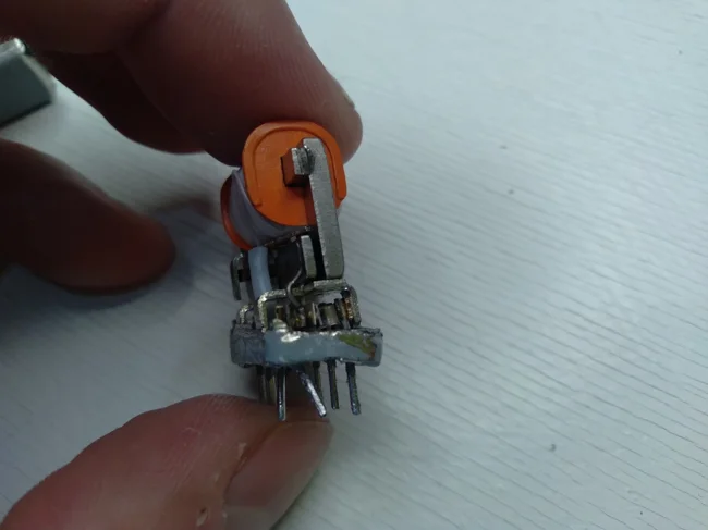
Another photo of the anchor and contact group from a different angle
Since this relay is designed to switch two circuits, then with the help of one coil, two anchors and two contact groups are controlled. One of them is located in the front part of the relay, and the second in the back.


